
 EN

A Gearless Motor is not simply a conventional motor with one component removed. It changes how torque, speed, motion control, service work, and installation risk are distributed across a machine. In a traditional gear-motor combination, a relatively high-speed motor works through a reducer to obtain the output speed and torque the driven equipment needs. A Gearless Motor, often configured as a direct-drive machine, is selected or designed to produce usable output torque without that reduction stage.
That architectural difference can simplify a machine, but it does not make one option automatically better. As a technical selection question, the useful comparison is not “new versus old.” It is whether the load, duty cycle, required speed range, installation envelope, controls, and service model favor a Gearless Motor or a motor-plus-gearbox system.
Start with the power path
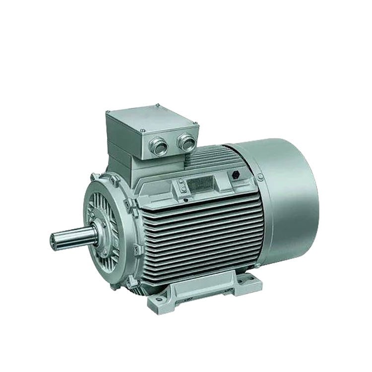
A traditional gear-motor combination has three main functions: the motor creates mechanical power, the gearbox trades speed for torque, and couplings or other transmission parts deliver that output to the load. Gear ratios let designers use common motor speeds while obtaining slower output rotation. This remains a practical arrangement for conveyors, mixers, hoists, and many other machines whose output speed is well below the motor’s efficient operating speed.
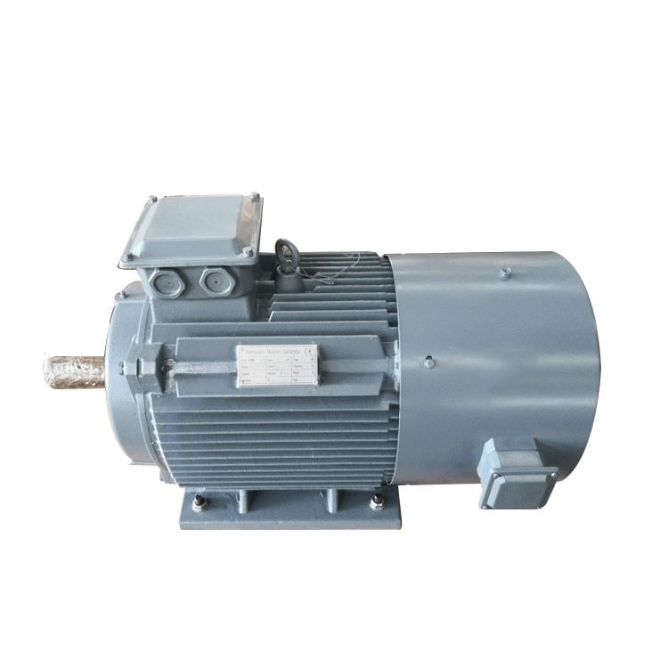
A Gearless Motor places the motor’s torque directly at, or close to, the load shaft. In direct-drive layouts, the motor is typically sized for lower speed and higher torque than the motor in a geared arrangement. There is no gear mesh between rotor and driven load. The result can be a shorter mechanical power path, but the motor, drive, feedback device, bearings, and mounting structure now carry more of the performance responsibility.
1. Speed and torque are achieved differently
With a gear-motor, the ratio supplies mechanical multiplication. A small, fast motor can drive a slow, high-torque load because the reducer converts speed into torque. With a Gearless Motor, torque must be generated electromagnetically at the required output speed. This can require a larger diameter motor, a higher-torque motor topology, or careful thermal design.
For this reason, compare the full load profile rather than only rated kW. A Gearless Motor may fit a low-speed, continuously controlled load very well, while a geared package may remain more compact or economical when the duty is straightforward and a standard ratio is available. Peak torque, breakaway torque, inertia, acceleration time, overhauling load behavior, and hours at low speed all belong in the calculation.
2. Mechanical losses and maintenance points change
A gearbox introduces gear contact, bearings, seals, lubricant, and often a service routine for oil condition, leakage, backlash, and vibration. The exact workload depends on gearbox construction and duty; no universal service interval should be assumed. Still, each added mechanical stage is another component set to inspect.
A Gearless Motor removes the gearbox and its gear-mesh losses from the path. Fewer transmission components can reduce alignment interfaces and lubricant-related tasks. But “gearless” does not mean maintenance-free. A Gearless Motor still needs appropriate bearing care, cooling-path cleanliness, electrical connection checks, mounting inspection, and control-system diagnostics. In real plants, service access and diagnostic capability often matter as much as the component count.
3. Efficiency must be assessed as a system
It is reasonable to expect a Gearless Motor to avoid gearbox losses, especially where a reducer would run for many hours. However, the motor’s own efficiency curve, the inverter, control tuning, and operating point determine the total result. A poorly matched direct-drive machine operating far from its favorable region may not deliver the expected advantage.
The same caution applies to geared solutions. A well-matched motor and high-quality reducer can be a sound system for a fixed-speed or limited-speed duty. The better question is: at the speeds and torques the machine will actually see, which complete system has lower losses and acceptable temperature rise? Estimate that using the duty cycle, not a single catalog rating. Anyway, the point is not which technology is newer—it is which one fits the actual site constraints without creating a maintenance headache two years down the line.
4. Control precision and dynamic response differ
A Gearless Motor can eliminate gearbox backlash and torsional compliance from the drive train. That can help applications needing smooth low-speed motion, repeatable positioning, rapid reversal, or responsive torque control. A Direct Drive Motor arrangement is therefore often considered where the load must respond directly to the control loop.
Traditional gear-motor combinations can also be controlled effectively, but the gearbox ratio, backlash, reflected inertia, and mechanical resonance need to be considered. In a Gearless Motor system, direct coupling also makes load disturbances more visible to the motor and controller. Control tuning, encoder feedback where needed, and structural stiffness deserve early attention rather than being left to commissioning.
5. Installation and space trade-offs are not one-sided
Eliminating a reducer can shorten a drivetrain and reduce the number of aligned components. That may simplify installation in a constrained machine layout. Conversely, a Gearless Motor capable of high torque at low speed can be physically larger or heavier than the smaller high-speed motor it replaces. Its mounting face, shaft interface, bearing loading, and heat rejection must be checked as an integrated assembly.
A gear-motor can offer convenient standardized mounting forms and familiar replacement practices. For retrofits, it may be easier to keep an established reducer footprint. For new equipment, a Gearless Motor can be more attractive if the whole machine can be designed around a direct-coupled layout from the beginning.
6. Electrical integration becomes central for direct drive
Many Gearless Motor applications rely on a variable-frequency drive or servo drive to provide the desired speed and torque control. This makes the drive, cable length, grounding, motor insulation, and bearing-current mitigation part of the selection rather than afterthoughts. NEMA MG 1 Part 31, for example, addresses inverter-fed machine considerations such as voltage spikes and shaft-voltage-related bearing protection. That is a design checkpoint, not a claim that every motor has a particular rating.
Before looking at rated power output, ask what the load actually demands at low speed, how often it reverses, and whether the controller can protect the motor through all operating modes. A Gearless Motor with poorly specified controls can lose the mechanical simplicity it was meant to deliver.
The ENNENG Customisation Advantage
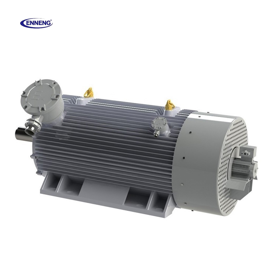
No two industrial facilities share the same spatial or mechanical constraints. ENNENG stands out because we do not just supply off-the-shelf catalogue products; we specialise in delivering a tailor-made permanent magnet motor tailored to your specific application .
Supported by our elite R&D team consisting of engineers from the National Rare Earth Permanent Magnet Engineering Centre, and backed by dozens of patents, we customise high-voltage (6kV/10kV) and low-voltage (380V/660V/1140V) solutions to match your existing footprint. From water treatment facilities and oil wells to explosion-proof mining environments, we deliver optimal performance where general-purpose motors fail.
If you are evaluating commercial permanent magnet motors for sale and need an engineered drive solution that guarantees efficiency and longevity, ENNENG is your trusted partner.Contact ENNENG Today.Speak to our technical engineering team to receive a customised drive proposal.
- WhatsApp: +86 18562780228
- E-Mail: [email protected]
- Phone: +86 532 66000559