
 EN

In a distributed industrial power system, the load rarely behaves like a steady laboratory resistor. A conveyor may start, a pump may cycle, a welding station may pulse, and an inverter-driven motor may suddenly stop drawing power. The useful question is not whether a Permanent Magnet Generator PMG can produce electricity. It is whether the generator, converter, protection, and controls can keep the usable bus stable when demand changes faster than the prime mover can react.
As a renewable-energy engineer reviewing load curves and commissioning reports, I start with the duty cycle rather than the nameplate. That distinction matters because a Permanent Magnet Generator PMG has a fixed magnetic field. It cannot raise or lower rotor excitation in the same way as a wound-field alternator. Its adaptation to unstable load conditions therefore comes from a coordinated system: mechanical inertia, electrical machine design, power electronics, energy buffering, and staged load control.
Why Unstable Loads Challenge a Permanent Magnet Generator PMG
Generator voltage and frequency are linked to rotor speed and machine characteristics. When an industrial load increases abruptly, electrical torque rises. If the engine, turbine, hydraulic drive, or other prime mover does not immediately provide matching torque, speed falls. In a direct AC arrangement, that can pull frequency and terminal voltage down. A sudden load rejection can have the opposite effect: speed and voltage may rise until the controller sheds input power, diverts energy, or applies braking.
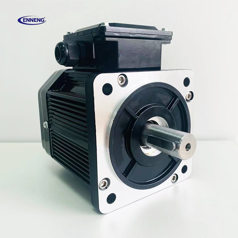
The key point is that a PMG is not inherently unstable. It responds quickly because it has no rotor field circuit to build up. But that fast electromagnetic response does not remove the energy-balance problem. The system still needs somewhere for the energy to come from during a load step and somewhere for it to go during a load rejection.
This is often misread as a generator-size issue only. More precisely, it is a matching issue among the generator’s transient capability, the prime mover’s torque-speed curve, the converter rating, the DC-link or storage capacity, and the load sequence. A unit that looks adequate at rated power may still give poor process continuity if those pieces are not coordinated.
How the Power-Electronic Interface Creates Adaptability
For variable-speed distributed generation, the common architecture is PMG AC output, rectification to a DC bus, and inversion to the voltage and frequency required by the industrial loads. A controlled or active rectifier can regulate generator current, while the inverter holds the downstream AC bus within its programmed limits. This separates generator speed from the output frequency seen by the plant.
During a positive load step, the inverter senses a DC-bus tendency to dip and increases its power request. The rectifier controller requests more generator current within safe limits. A brief voltage excursion can still occur; the aim is a controlled recovery rather than an unrealistic promise of zero deviation. During a load rejection, the control system reduces electrical loading on the PMG and must manage excess mechanical input through prime-mover control, a dump load, storage charging, or braking.
A diode rectifier can be appropriate for simpler applications, but it offers less controllability over current and DC-bus behavior than an active front end. The right choice depends on the site’s load dynamics, harmonic limits, fault strategy, maintenance capability, and budget. If your priority is process continuity through frequent load steps, the factor to evaluate first is the complete converter-control package, not the PMG alone.
Mechanical Design Still Matters During Fast Transients
Electrical controls work within physical limits. Rotor inertia supplies or absorbs energy for a short interval, but too little inertia can make speed move quickly after a step change. Too much inertia may slow the system’s ability to follow an available variable energy source. Coupling stiffness, torsional modes, overspeed limits, and the response of the governor or turbine controller also affect the outcome.
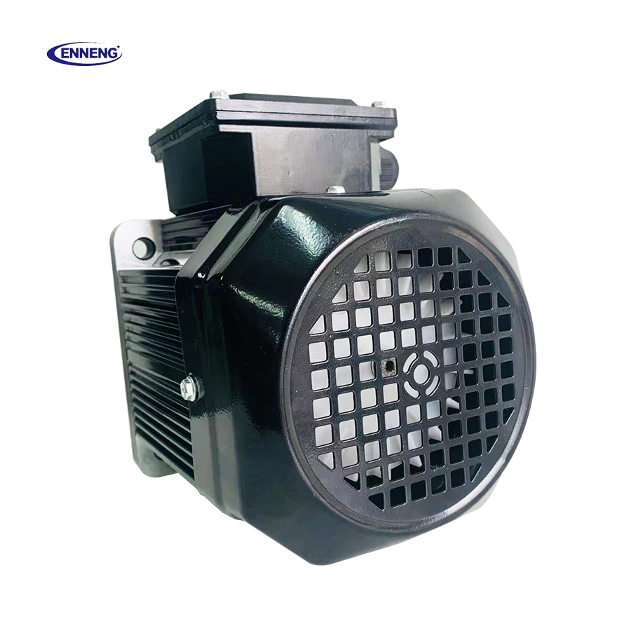
Direct-drive Permanent Magnet Generator PMG configurations can reduce mechanical failure points by eliminating a gearbox in suitable applications. That is valuable in remote or difficult-to-service industrial sites, although direct drive does not eliminate the need to assess torque ripple and shaft dynamics. Once you account for ambient temperature, altitude, enclosure cooling, and the actual duty cycle, nameplate power is not the same as continuous site capability.
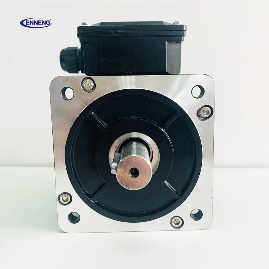
The same thinking applies when a Permanent Magnet Motor PMSM is part of the load. A PMSM controlled by a variable-frequency drive may create rapid changes in power demand during acceleration, deceleration, or regenerative braking. Coordinating drive ramp rates and regeneration handling with the generator-side controller prevents one part of the microgrid from forcing another into an avoidable trip.
Four Design Measures for Unstable Industrial Loads
1. Build a realistic load-step profile
List the largest motor starts, welding cycles, compressor transitions, regenerative events, and simultaneous operations. Record starting method, expected ramp time, power factor behavior, and duration. Do not size only from the sum of steady-state kW. The shift that changes a specification exercise is realizing that peak rating matters only if the generator and its controls can support the actual time profile of that peak.
2. Reserve transient current and converter headroom
Specify continuous and short-duration current limits separately for the PMG, rectifier, inverter, cables, and protection devices. Converter overload capacity is useful only when thermal limits, DC-bus voltage limits, and the prime mover can support it. Commissioning should verify the response to representative load steps rather than assuming that an advertised overload percentage applies to every installation.
3. Add energy buffering and a safe energy-rejection path
DC-link capacitors handle very short disturbances. Batteries, supercapacitors, flywheels, or other storage can cover longer gaps between a load change and prime-mover response. For oversupply or sudden load loss, a controllable dump load, braking resistor, storage charger, or input-power reduction path may be necessary. The correct combination depends on the energy magnitude and duration, not on a generic product preference.
4. Coordinate controls and protection settings
Set sensible limits for DC-bus voltage, generator current, speed, inverter overload, frequency, and load shedding. Use staged priorities so that noncritical loads disconnect before essential controls or safety equipment. Avoid protection settings that fight each other: for example, an overly fast generator-current limit paired with an inverter undervoltage trip can turn a manageable event into an outage.
A Commissioning Sequence That Reveals Weak Points
- Verify polarity, grounding, insulation, and sensor scaling before energizing the full system.
- Run the prime mover and Permanent Magnet Generator PMG through the expected speed range with no process load.
- Apply controlled resistive and inductive steps, observing speed, AC current, DC-bus voltage, output voltage, and recovery time.
- Repeat tests for the real high-impact equipment, including the ramp profile of each Permanent Magnet Motor PMSM drive.
- Test load rejection, storage charging limits, dump-load operation, and staged shedding under supervised conditions.
- Record alarms and trends so future maintenance teams can distinguish an aging mechanical problem from a control-setting problem.
Conditions matter. A control setting that is stable with a warm engine and a partially loaded workshop may need adjustment at low ambient temperature, high altitude, or after a production expansion. This is why field acceptance testing should be treated as part of generator adaptation, not as an afterthought.
What to Ask Before Selecting the System
- What are the largest positive and negative load steps, and how often do they occur?
- How quickly can the prime mover add or remove torque?
- Will the output be a direct AC bus or a regulated DC bus followed by an inverter?
- Which loads are critical, deferrable, or safe to shed?
- How will regenerative energy from a Permanent Magnet Motor PMSM or other drive be absorbed?
- What ambient conditions require derating, and what monitoring will be available after commissioning?
There is no universal answer here. A modest, predictable load may work well with a simple arrangement, while a site with frequent starts, regeneration, and varying prime-mover speed generally benefits from more capable conversion, buffering, and supervisory control. The most reliable Permanent Magnet Generator PMG installation is the one specified around measured load behavior and verified with transient tests—not one selected from steady-state kW alone.