 EN

A Retrofit Induction to PMSM project can look straightforward on a replacement schedule: remove the legacy induction motor, fit a permanent magnet synchronous motor, reconnect the drive, and commission. On an operating site, that assumption is often what creates delay. The proposed Permanent Magnet Motor PMSM may be technically attractive, but construction progress depends on whether its mechanical, electrical, thermal, environmental, and operational interfaces match the installed system.
The practical question is not “Is a PMSM more efficient?” It is “Can this motor be installed and placed into safe service within the available outage?” The answer comes from a site survey and an application review completed before the crew is mobilized. The following restrictions are the ones most likely to stop, extend, or rework a Retrofit Induction to PMSM installation.
1. Mounting, shaft, and coupling geometry may not be interchangeable
The first construction gate is physical fit. Frame designation alone does not prove that a Permanent Magnet Motor PMSM will bolt into the same location as the induction motor. Confirm the foot-hole pattern, shaft height, flange type, shaft diameter and length, key dimensions, axial clearance, and permitted overhung or thrust load. Also inspect the coupling hub, belt sheave, guard, baseplate, grout, and alignment adjustment range.
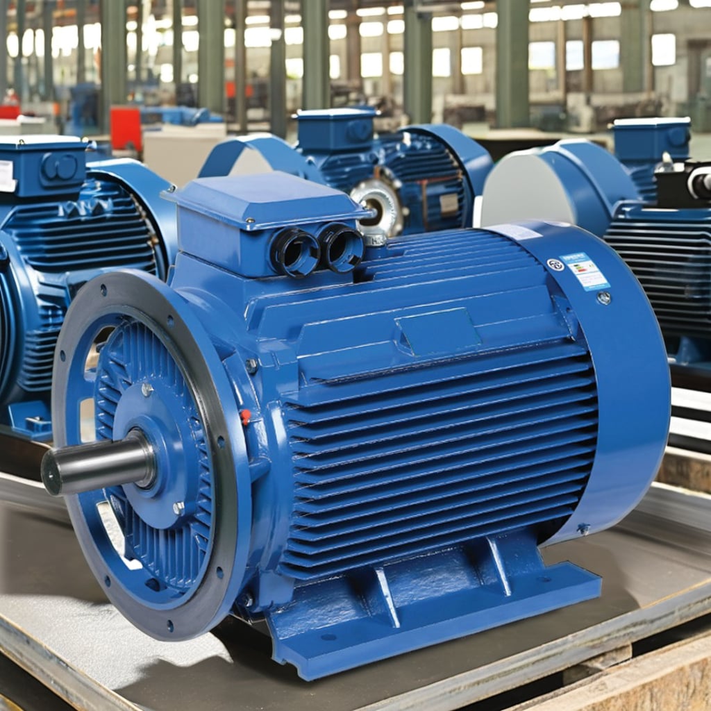
Small dimensional differences can become large schedule problems. A motor that cannot accept the existing hub may require machining; an altered shaft centerline may call for shims or a revised base; a longer body may collide with a guard, wall, pipe rack, or service walkway. None of those items is a reason to reject a retrofit automatically, but each must be resolved in the work package rather than discovered during the outage.
2. The driven load and duty cycle can restrict motor selection
A Retrofit Induction to PMSM should be sized from the actual load profile, not only the legacy nameplate. Pumps, fans, compressors, conveyors, mixers, and hoists impose different starting torque, speed, inertia, shock-load, and cycling demands. Record normal and maximum torque, required speed range, starts per hour, acceleration time, operating hours, and any process condition that causes overload.
This matters because the replacement motor, drive, and load form one system. A Permanent Magnet Motor PMSM suited to variable-speed pump duty may need a different torque-speed envelope from one serving a high-inertia conveyor. If the survey reveals a duty point outside the proposed motor’s continuous thermal or torque capability, engineering may need to revise the motor, gearing, control logic, or process sequence before construction can continue.
3. Existing VFD and controls may not be compatible
A PMSM is not simply an induction motor with a different rotor. Its drive must support the intended motor-control mode, provide suitable parameterization, and operate within the motor’s voltage, current, speed, and feedback requirements. Retaining an existing VFD without checking its PMSM capability is a common source of commissioning delay.
Review the drive model and firmware, motor-control options, encoder or sensorless requirements, braking method, safe-torque-off interfaces, network communications, and available commissioning tools. Then assess cable length, output filtering, grounding, insulation coordination, and bearing-current mitigation as applicable. Guidance for converter-fed AC machines, including NEMA MG 1 Part 31 and IEC TS 60034-25, is useful here because it frames the drive, cable, and motor as an application system rather than independent purchases.
If a new VFD or control panel is needed, construction can also be held back by panel space, short-circuit rating, upstream protection changes, control wiring routes, and the time required for site acceptance testing. Verify these interfaces early.
4. Supply quality and electrical-area rules can stop energization
Before the motor is delivered, verify the site supply voltage, frequency, grounding arrangement, fault level, harmonics, and available capacity. The site may also impose rules on cable type, gland selection, conduit fill, bonding, arc-flash labeling, isolation points, and lockout/tagout procedures. These are construction constraints, not paperwork to leave until commissioning.
Where the motor is installed in a classified, corrosive, wet, dusty, or washdown area, the enclosure and all associated fittings need to match the site requirement. A general-purpose enclosure cannot be assumed suitable for a hazardous or high-ingress environment. Confirm the area classification, ambient conditions, required ingress protection, cable-entry method, and local approval pathway with the site’s responsible electrical authority.
5. Thermal conditions and cooling clearance may be inadequate
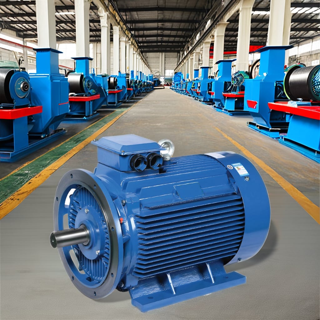
Motor ratings are meaningful only under their stated conditions. High ambient temperature, altitude, dust loading, restricted airflow, radiant heat, vibration, and frequent low-speed operation can reduce the thermal margin of a Permanent Magnet Motor PMSM. Enclosed equipment rooms often add another limitation: there may be too little room around the motor for cooling air, inspection, or removal.
Measure or obtain the expected ambient range and inspect the ventilation path before final selection. Check whether the intended duty includes long periods at low speed, where shaft-mounted cooling can be less effective, and whether auxiliary cooling or another thermal arrangement is needed. The practical lesson is simple: a nameplate rating is a planning input, not proof that the installed environment is acceptable.
6. Access, lifting, and outage windows can dominate the schedule
Some projects are electrically feasible but not constructible within the shutdown window. Restricted access can prevent a crane, forklift, chain block, or rigging crew from reaching the motor. Other sites limit hot work, noise, work at height, confined-space entry, or simultaneous operations. A motor change may also require a process isolation sequence that only operations personnel can authorize.
Plan the route from delivery point to foundation, lifting points, rigging capacity, removal of the old motor, temporary storage, alignment work, cable termination, rotation checks, and controlled return to service. Ask a direct question: if alignment, a coupling bore, or drive parameters need correction, is there enough outage contingency to do that safely? If not, split the work into a pre-outage preparation phase and a shorter final changeover.
7. Documentation gaps create avoidable rework
An incomplete legacy record can be a site-matching restriction by itself. Teams need the current single-line diagram, motor and VFD nameplates, wiring diagrams, protection settings, mechanical drawings, coupling data, foundation details, process load information, and site safety requirements. If these records conflict with field measurements, use the field condition as the escalation trigger—not as a reason to improvise.
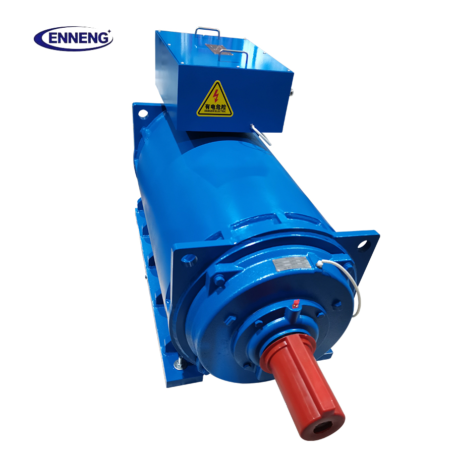
Qingdao Enneng Motor Co., Ltd. supports permanent magnet motor and new-energy equipment applications; however, final selection should be based on confirmed site data and the responsible engineer’s review. A supplier can help compare winding voltage, mounting, thermal arrangement, and speed-torque information, but cannot replace the site’s mechanical, electrical, and safety approval process.
Conclusion: release the work only after the interfaces agree
The biggest obstacle to a Retrofit Induction to PMSM is usually not the motor itself. It is the mismatch between the replacement package and the conditions already built into the site. Mechanical fit, the driven load, VFD behavior, electrical rules, thermal environment, access, and outage control all deserve a signed engineering check before installation begins.
When those restrictions are verified early, a Permanent Magnet Motor PMSM retrofit can move from a hoped-for efficiency upgrade to a controlled construction task. When they are not, crews may spend the outage waiting for adapters, revised controls, approvals, or a different motor configuration.
If you are evaluating commercial permanent magnet motors for sale and need an engineered drive solution that guarantees efficiency and longevity, ENNENG is your trusted partner.Contact ENNENG Today.Speak to our technical engineering team to receive a customised drive proposal.
- WhatsApp: +86 18562780228
- E-Mail: [email protected]
- Phone: +86 532 66000559