
 EN

A Retrofit Induction to PMSM project should begin with evidence, not a replacement order. A permanent-magnet synchronous motor can be a strong option when an existing driven system has the right duty cycle and control conditions, but the expected result depends on the motor, drive, mechanical interface, and process load working together. Before approving a Retrofit Induction to PMSM program, build a site-specific baseline and resolve the constraints that cannot be corrected during a short shutdown.
From an application-engineering viewpoint, the first question is not “Which motor has the higher catalog efficiency?” It is: what does this machine actually do across a shift, a season, and a production cycle? That distinction keeps a Retrofit Induction to PMSM decision grounded in operating evidence instead of a nameplate comparison.
1. Define the renovation objective and the decision boundary
Write down why the Retrofit Induction to PMSM project is being considered. Common objectives include reducing energy use at partial load, improving speed control, addressing recurring motor failures, freeing panel capacity, or meeting a site efficiency requirement. Rank the objectives, then define what success will look like: lower kWh per unit produced, stable process speed, fewer trips, or a documented maintenance improvement.
Set the boundary around the whole motor-driven system. Include the driven equipment, coupling or transmission, VFD if present, process controls, electrical supply, cooling conditions, and maintenance access. IEC materials on electric motors emphasize that system savings depend on matching efficient components to the required load. That is why a Retrofit Induction to PMSM assessment cannot stop at the motor rating.
2. Collect an operating baseline, not only nameplate data
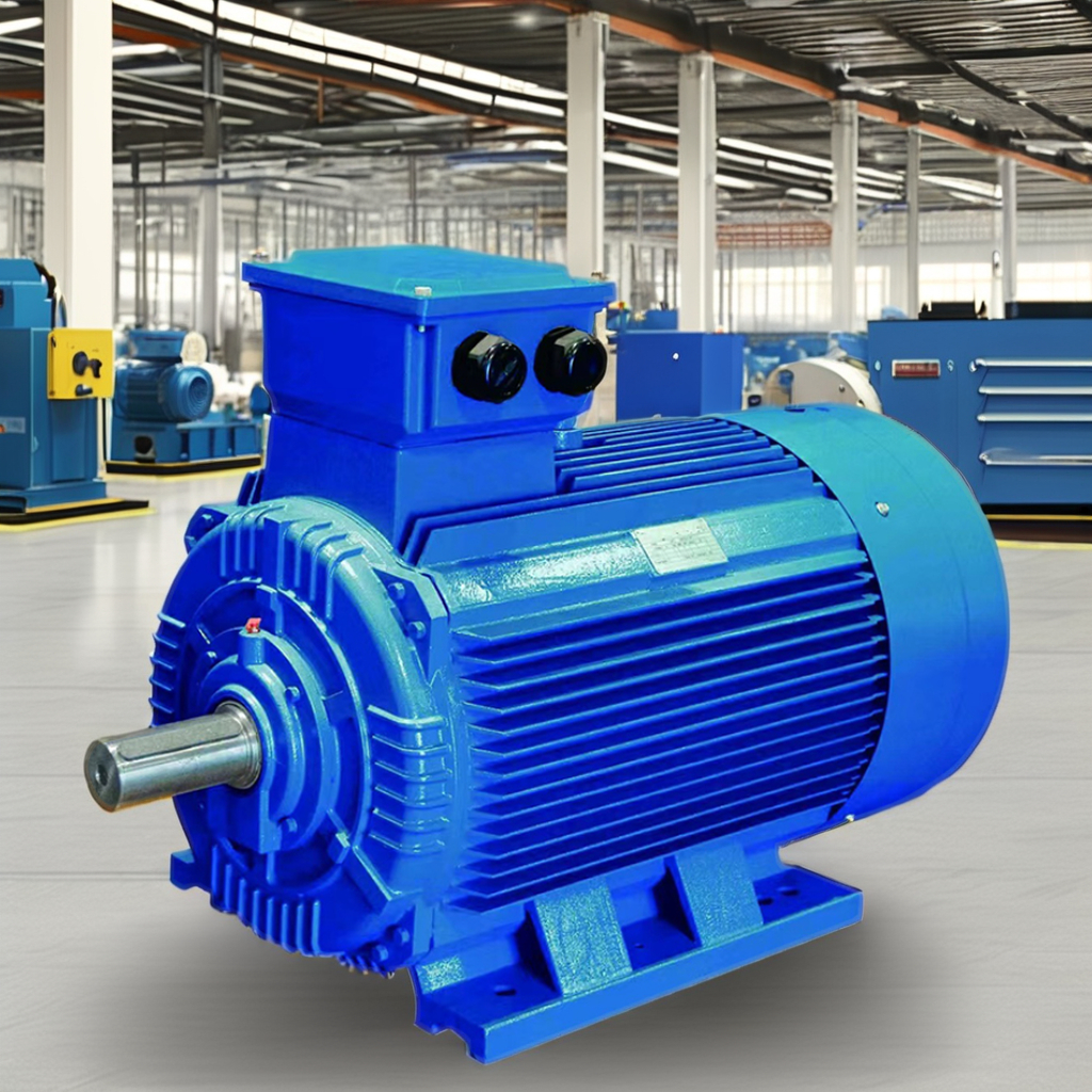
For every candidate machine, photograph and transcribe the installed motor nameplate: rated power, voltage, frequency, current, speed, duty, insulation class, enclosure, mounting arrangement, frame size, and efficiency marking. Confirm whether the motor is direct-on-line or drive-fed. Then record the driven-machine nameplate and any gearbox, belt, or coupling details.
The more valuable part of Retrofit Induction to PMSM pre-evaluation is the operating record. Trend real current, power, speed, run hours, starts per hour, production state, ambient temperature, vibration observations, and unplanned stoppages. Use a representative production window rather than a single convenient reading. A motor that looks lightly loaded in one snapshot may see regular torque peaks, while another may spend most of its life below rated load where the proposed Permanent Magnet Motor PMSM configuration could behave differently.
- Capture minimum, typical, and peak process demand.
- Identify continuous, intermittent, cyclic, and high-inertia duty.
- Record voltage imbalance, harmonic concerns, and supply interruptions.
- Separate production-related load changes from operator workarounds.
3. Build the torque-speed and load-inertia picture
A Retrofit Induction to PMSM proposal needs a torque-speed review before a supplier selection or shutdown plan. Obtain pump, fan, compressor, conveyor, mixer, hoist, or machine-builder curves where available. Establish breakaway torque, acceleration time, overload events, speed range, direction changes, and the reflected inertia at the motor shaft. For variable-torque equipment, verify how process demand changes with speed; for constant-torque duties, test the worst operating condition.
This step prevents a common mistake: equating rated kW with suitability. A Permanent Magnet Motor PMSM may be selected for an attractive efficiency class and still be unsuitable if its continuous torque, overspeed, thermal margin, or load inertia assumptions are wrong. Ask whether the driven system can coast safely, whether a restart under load is required, and whether the process permits a controlled ramp.
4. Verify mechanical interchangeability in the field
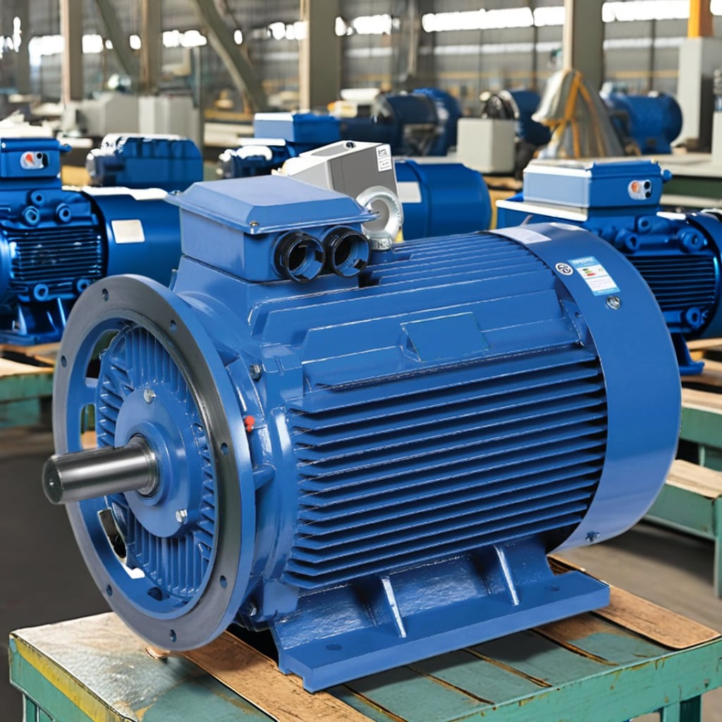
Do not assume a same-power Retrofit Induction to PMSM unit will be a bolt-in exchange. Measure the actual base holes, shaft height, shaft diameter and keyway, shaft extension, flange dimensions, coupling hub, guard clearances, and cable-entry direction. Check total motor length, lifting path, foundation condition, alignment provisions, and access for future bearing or fan service.
Frame compatibility is only the first gate. Assess the coupling and driven shaft for alignment tolerance, torsional behavior, and any need to rebalance rotating parts. If a gearbox is involved, confirm its permissible input speed and vibration limits. In practice, an adapter plate, modified guard, or revised coupling can determine the shutdown scope of a Retrofit Induction to PMSM project more than the motor itself.
5. Audit the VFD, controls, and protection scheme
Most successful Retrofit Induction to PMSM projects treat the drive and motor as a verified pair. Document the VFD make, model, firmware, power rating, overload duty, input conditions, output filters, motor cable length, braking arrangement, and available motor-control modes. Confirm that the chosen drive supports the proposed PMSM control method and that commissioning personnel can access the required parameters.
Review encoder or sensor requirements, feedback wiring, safe-torque-off circuits, PLC interlocks, emergency stops, and process permissives. Also examine motor thermal protection, earth-fault protection, and bearing-current mitigation where the application warrants it. Drive-fed operation can introduce harmonic-related losses, so rated efficiency alone should not be treated as a field result. A Retrofit Induction to PMSM plan should include an acceptance test under the real drive settings and process load.
6. Check thermal, environmental, and reliability constraints
Map the actual environment: ambient temperature, altitude, dust, washdown, humidity, corrosive vapor, outdoor exposure, and restricted airflow. Verify enclosure, cooling method, mounting orientation, and derating assumptions against the site. If the original induction motor survives only because it is oversized or has abundant airflow, the Retrofit Induction to PMSM evaluation must preserve that margin rather than compare nominal ratings alone.
Review failure history with maintenance teams. Look for bearing failures, misalignment, insulation damage, repeated overload trips, contamination, cooling blockage, and poor cable terminations. A new Permanent Magnet Motor PMSM will not cure a mechanical or process problem that has not been identified. Turn each known failure mode into an inspection or acceptance item.
7. Validate energy and business assumptions transparently
Use measured baseline power and operating hours to model the Retrofit Induction to PMSM case. State every assumption: expected load profile, proposed efficiency at relevant points, electricity price, downtime allowance, installation labor, VFD or control changes, mechanical adaptation, and maintenance impact. Present a range, not a single projected saving. The model should distinguish motor losses from system losses and should show what measurement will confirm performance after commissioning.
For compliance-oriented projects, retain nameplate records, test information, and the applicable customer or regional requirement. IEC references identify IEC 60034-2-1 as a motor test basis and IEC 60034-30-1 as an efficiency-classification scheme, but the project team should verify the edition and applicability for its own market and drive-fed duty. Do not transfer an efficiency label from one operating condition directly to another.
8. Prepare the installation, commissioning, and acceptance plan
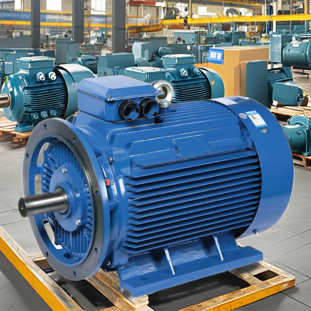
Before releasing the Retrofit Induction to PMSM order, create a shutdown method statement. It should cover isolation, removal and lifting, foundation repair, alignment, cabling, parameter backup, VFD configuration, rotation check, unloaded run, loaded run, vibration and temperature checks, and operator handover. Identify spares, special tools, and the technical contact responsible for each gate.
Define acceptance criteria before work starts: correct rotation, stable process control, current and temperature within agreed limits, no abnormal vibration or noise, functional protections, and a comparison of pre- and post-retrofit measurements at comparable production conditions. This turns a Retrofit Induction to PMSM renovation from an equipment change into a controlled engineering improvement.