
 EN

Walk past a rotary kiln, sugar-mill crusher, or chemical extruder turning at fifteen revolutions per minute, and the loudest part on the pad is rarely the driven drum—it is the multi-stage reduction gearbox between the motor and load shaft. Every intermediate pinion, belt pulley, chain sprocket, and grid coupling takes a cut of the electrical input before torque reaches the process. Replacing that mechanical chain with a Direct Drive Motor puts electromagnetic torque generation straight onto the load shaft, stripping out intermediate friction stages completely.
Plant maintenance crews know the hidden price of speed reducers: sheared coupling bolts during cold breakaway starts, contaminated gear oil, and 5% to 15% of nameplate power vanishing as sump heat. ENNENG tackles this drivetrain inefficiency at the root by building multi-pole permanent magnet machines designed for low-speed shaft duty. Integrating an ENNENG Direct Drive Motor into low-speed high-torque equipment removes mechanical transmission loss while freeing technicians from endless reducer rebuilds.
Where Mechanical Transmission Loss Drains Conventional Drive Trains
A standard geared drivetrain converts electrical kilowatts into high-speed shaft rotation—typically 1,500 or 1,800 RPM—only to step that speed back down through two or three stages of helical or planetary gearing. Evaluating the entire power path from the variable frequency drive (VFD) terminals to the driven roll exposes why intermediate hardware bleeds away energy.
Gear-Mesh Friction, Oil Churning, and Belt Slip
Published AGMA 2001 and ISO/TR 14179 gear thermal ratings show that each reduction stage loses 1.5% to 3% of transmitted power at full load, while V-belts, chains, and couplings drop another 2% to 5% through flexing hysteresis and slip. Worse yet, lubricant churning and seal drag inside a large sump remain nearly constant even when throughput drops to 40%. A Direct Drive Motor bypasses these parasitic drag points, routing energy straight from the stator air gap into the load shaft.
High-Pole Electromagnetic Design Without Rotor Excitation Waste
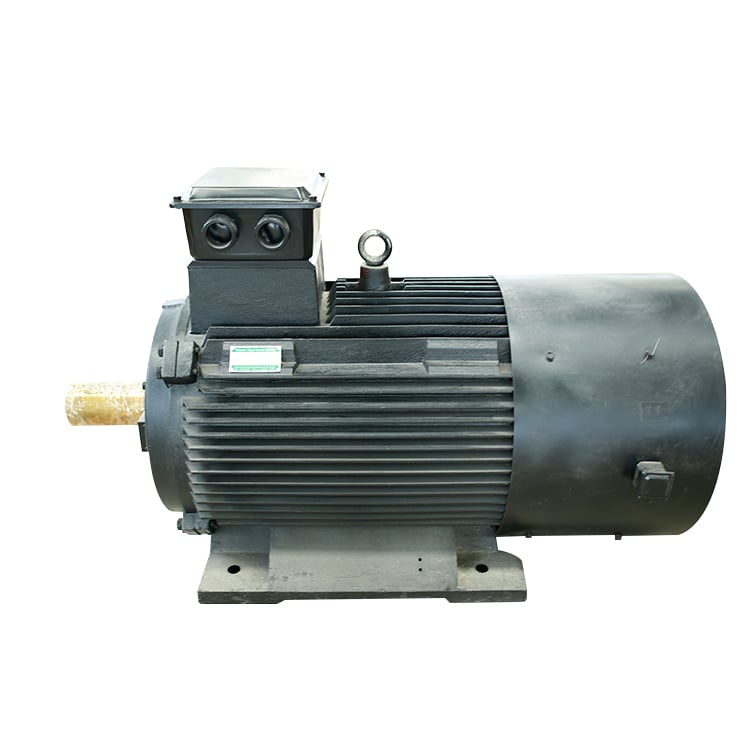
Instead of spinning a 4-pole squirrel-cage rotor fast and gearing it down, an ENNENG Direct Drive Motor uses a high-pole rotor geometry loaded with sintered NdFeB rare-earth magnets. Standard induction rotors must slip behind the stator field to induce current into rotor bars, burning kilowatts as heat. Because a synchronous ENNENG permanent magnet drivetrain generates magnetic flux without induced rotor currents, the Direct Drive Motor locks to the inverter frequency down to single-digit RPM while keeping operating temperature rise under 60K (20K cooler than equivalent induction frames).
System-to-System Comparison: Geared Drive vs. Gearless Motor Architecture
Comparing a motor nameplate in isolation misses the losses buried downstream in couplings and reducers. Under IEC 61800-9-2 Complete Drive Module and Power Drive System energy standards, engineering teams must weigh the footprint, control stiffness, and partial-load behavior of the whole Direct Drive Motor assembly.
|
Metric |
Geared Induction |
ENNENG Direct Drive Motor |
Impact on Heavy Machinery |
|
Torque Path |
Motor to multi-stage reducer |
Shaft coupled straight to load |
Eliminates 5% to 15% mechanical transmission loss |
|
Load Efficiency |
Drops below 60% load |
Flat curve across 25% to 120% load |
Delivers 5% to 30% electricity savings |
|
Power Factor |
0.72 to 0.85 PF |
0.95 to 1.00 PF (>10% current drop) |
Frees transformer kVA and cools cables |
|
Control |
Tooth backlash delays loop |
Zero backlash; synchronous lock |
Prevents hunting on indexing tables |
|
Acoustics |
78 to 92 dB gear whine |
Under 55 dB smooth rotation |
Meets ISO 20816 vibration limits |
Eliminating Torsional Backlash in Precision Low-Speed Processes
On plastic extruders, rotary indexing tables, and paper-mill calendar rolls, gear tooth clearance introduces mechanical deadband between the motor encoder and the driven shaft. Whenever load torque reverses or surges, shaft wind-up causes speed hunting and gauge variations. Coupling a Direct Drive Motor directly to the process roll removes intermediate torsional compliance, letting the VFD closed-loop vector controller hold exact angular velocity.
Engineering Checks Before Replacing a Reducer with a Direct Drive Motor
Removing a gearbox changes how load inertia, breakaway friction, and radial overhang forces act on the motor bearings. Specifying a Direct Drive Motor for low-speed high-torque equipment requires practical engineering verifications before signing off on general arrangement drawings.
Sizing for Continuous Torque, Breakaway Peaks, and Thermal Derating
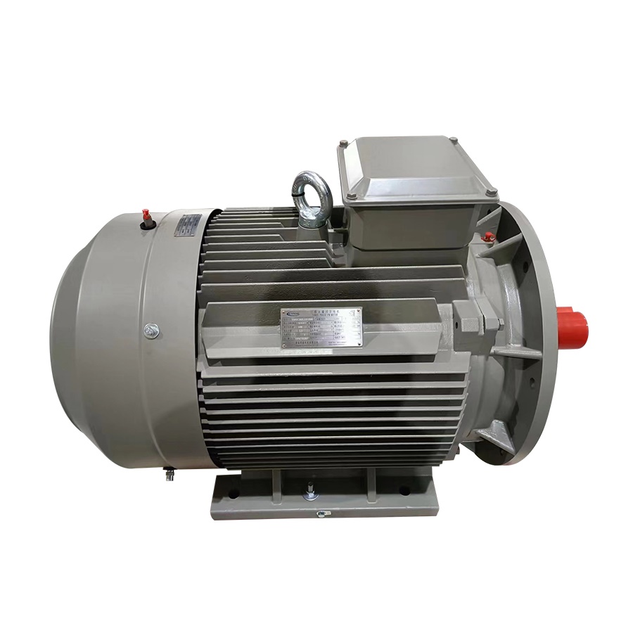
Never size a Direct Drive Motor from average kilowatt demand alone. Map the full torque-speed duty cycle: cold-slurry breakaway torque, acceleration time, continuous running torque, and stall-adjacent overload intervals. Because low-speed motors turn too slowly for shaft-mounted fans to move adequate cooling air at high torque, verify whether the Direct Drive Motor uses IC411 natural convection, IC416 forced-air blowers, or IC71W water-jacket cooling under IEC 60034-6 to prevent winding hot spots.
Auditing Reflected Load Inertia and Frame Mounting Stiffness
A gearbox divides reflected load inertia by the square of its reduction ratio. Stripping out the reducer exposes the Direct Drive Motor directly to the full rotational inertia of the heavy drum or mixer shaft. Confirm that the VFD current ceiling, DC-bus braking chopper, and baseplate stiffness can handle deceleration energy without resonance.
Field Commissioning and Preventative Care Protocol
- Verify Shaft Alignment and Concentricity: Use laser alignment tools on solid-shaft couplings or dial indicators on hollow-shaft shrink discs so radial runout never stresses the Direct Drive Motor bearings.
- Tune VFD Auto-Tuning at Standstill: Execute stator resistance and rotor pole-position routines on the Direct Drive Motor under NFPA 70 (NEC) protection rules before applying load, ensuring 150% to 200% breakaway torque.
- Enforce Lockout Safety and Grounding Audits: Follow OSHA 1910.147 lockout/tagout rules during coupling work—since permanent magnet rotors generate back-EMF whenever turned—and inspect shaft grounding rings every six months via ENNENG engineering support.
Industrial Retrofits and Custom Drivetrain Engineering from ENNENG
Across unified generator and motor ratings spanning 5kW to 5MW (110V to 690V)—alongside 1kW to 10kW vertical axis wind turbines (3kW, 5kW, and 10kW focus) for green microgrids—ENNENG customizes Direct Drive Motor frames to fit bedplates in cement, mining, chemical, and pulp plants. When radial loads or tight clearances rule out catalog reducers, ENNENG engineers hollow-shaft or flange-mounted Direct Drive Motor solutions that drop onto the driven shaft.
To evaluate torque curves and payback calculations for upcoming upgrades, contact the ENNENG team:
- WhatsApp: +86 18562780228
- E-Mail: [email protected]
- Phone: +86 532 66000559
FAQ
Q: Why does a Direct Drive Motor save energy compared to a high-speed induction motor with a gearbox?
A: A Direct Drive Motor eliminates both squirrel-cage rotor copper losses and multi-stage gearbox friction, oil churning, and coupling slip. By generating high torque at low RPM directly on the driven shaft with a 0.95 to 1.0 power factor, an ENNENG system removes 5% to 15% mechanical transmission loss and cuts total drivetrain electricity use by 5% to 30.
Q: When is a Gearless Motor the right technical choice for low-speed high-torque equipment?
A: A Gearless Motor is ideal when industrial machinery operates continuously below 300 RPM with high torque demand, frequent gearbox maintenance downtime, or strict speed-control requirements. ENNENG customizes Direct Drive Motor frames from 5kW to 5MW across 110V to 690V networks with natural, forced-air, or water-jacket cooling to match tight installation footprints.