 EN

A Mining Industrial Motor has to deliver torque in conditions far less controlled than a typical factory floor. Crushers bite into uneven rock, conveyor belts start under loaded conditions, screens transmit repeated impacts, and mills can introduce sudden changes in resistance. In those situations, shock resistance is not a decorative specification. It is part of the motor’s ability to preserve alignment, protect its electrical system, and return to stable operation after a mechanical upset.
As an engineer reviewing motor configurations, I would start with the duty cycle and the driven machine rather than with a nameplate alone. A motor that looks acceptable at steady rated load can still be poorly matched to a process that produces starts, stops, jams, impact loading, and persistent vibration. The practical question is not simply whether the motor runs; it is whether the Mining Industrial Motor can tolerate the real mechanical events that occur between planned maintenance windows.
Mining production creates more than a vibration problem
Shock and vibration overlap, but they are not the same design issue. Vibration is usually a repeated oscillation that can be measured and evaluated over time. Shock is a short-duration, high-energy event: a conveyor may see a sudden belt load, a crusher may encounter hard or oversized material, or a coupling may experience a torsional disturbance during a restart. Both can affect a motor, yet a vibration limit by itself does not prove that the machine will tolerate impact-driven events.
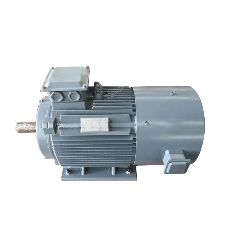
Mining machinery commonly includes crushers, mills, hoists, conveyors, grinders, and material-handling equipment. These applications combine variable load, contamination, continuous or extended duty, and mechanical disturbance. A Mining Industrial Motor must therefore be considered as part of a drive train, including its base, fasteners, coupling, gearbox, driven machine, and controls.
IEC 60034-14 addresses measurement, evaluation, and limits for mechanical vibration in rotating electrical machines. It is a useful reference when defining acceptable vibration behavior, but procurement teams should treat it as one input in a broader duty assessment. Shock resistance also depends on how the motor’s structure, rotor system, bearings, terminals, and mounting arrangement respond when the process delivers a transient load.
Where shock damage begins inside the motor-drive system
Mounting and frame movement
When a foundation, baseplate, or foot mounting is not sufficiently rigid, a shock event can loosen fasteners or shift alignment. Even a small movement can increase coupling forces and bearing loading. Over time, that can turn a tolerable operating condition into a repeating source of vibration and heat. The solution is not just a heavier frame; it is a verified mounting arrangement with appropriate stiffness, fastener practice, and alignment control.
Bearings, shafts, and rotor dynamics
Mechanical shock is transmitted through the shaft and bearings before it becomes visible in a maintenance report. Repeated impacts can increase bearing stress, disturb lubricant films, or contribute to clearance and alignment problems. The effect depends on load direction, coupling type, speed, driven inertia, and the frequency of the events. That is why a Mining Industrial Motor specification should describe radial and axial loads, overhung loads where applicable, starting frequency, and the characteristics of the connected equipment.
Windings, terminals, and electrical connections
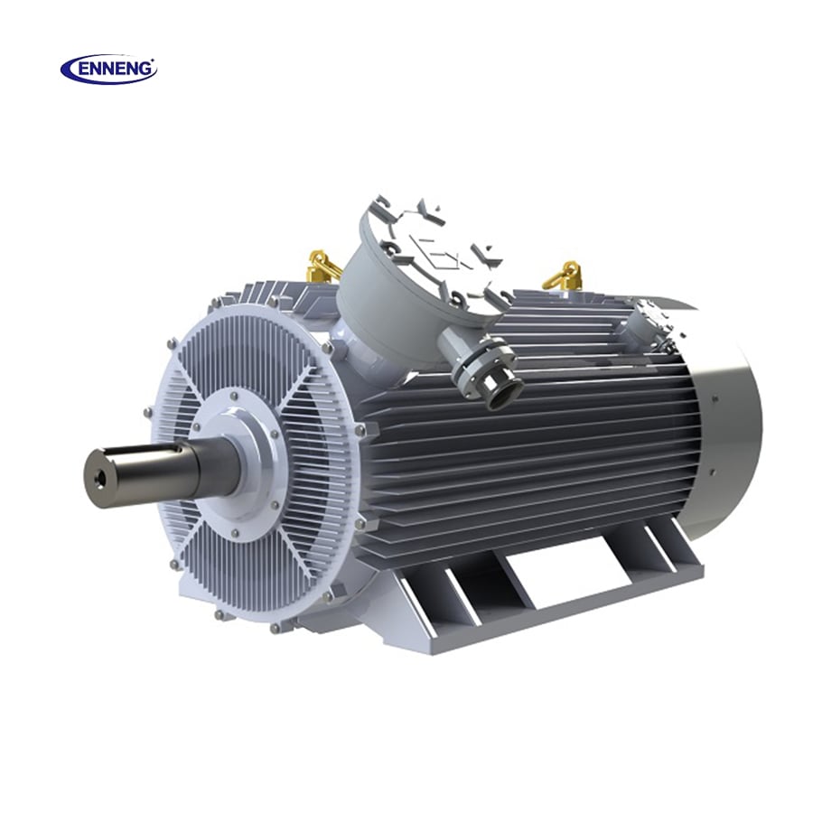
Shock does not remain purely mechanical. Movement at leads, terminal connections, cable entries, or internal supports can create electrical reliability concerns later. A design review should ask how leads are restrained, how terminal hardware is secured, and whether cable routing will transfer vibration into the enclosure. Dust and moisture can compound the problem if they reach areas that are already being stressed by movement.
Why permanent-magnet motor selection needs the same discipline
A Permanent Magnet Motor PMSM can be attractive where part-load efficiency and controllability matter, especially when paired with a properly configured drive. That does not make it automatically suitable for every mining duty. More precisely, motor technology should follow the load profile and mechanical environment, not replace their analysis. A Permanent Magnet Motor PMSM selected for a mining application still needs a shaft, bearing arrangement, frame, mounting, cooling approach, and control strategy that fit the shock exposure.
For variable-duty applications, high partial-load efficiency may be relevant to energy planning. However, it should be evaluated alongside starting torque, transient torque, acceleration time, load inertia, and the likelihood of jam-clearing or loaded restarts. If a process frequently applies abrupt torque changes, the drive settings and protective functions deserve as much attention as the motor’s rated output.
What to specify when shock resistance matters
The most useful specification turns a broad request for a “rugged” motor into conditions a supplier can review. Before selecting a Mining Industrial Motor, document the following:
- Driven-equipment events: Identify impacts, jams, loaded starts, rapid reversals, belt take-up changes, or material surges that can produce torque transients.
- Load path: State coupling type, gearbox arrangement, shaft orientation, radial and axial load expectations, and any overhung load.
- Installation conditions: Describe base stiffness, alignment method, ambient temperature, elevation, dust, moisture, washdown, and access for inspection.
- Duty and controls: Include run time, starts per hour, speed range, acceleration and deceleration requirements, and protective trips or torque limits.
- Acceptance criteria: Request a review of mounting, bearings, rotor balance, vibration requirements, terminal security, and documentation relevant to the actual application.
This level of detail gives the manufacturer a chance to identify application risks before equipment is installed. It also makes comparisons between motor proposals more meaningful than a simple comparison of rated power and efficiency class.
A practical verification conversation with the supplier
Ask the supplier to explain the load assumptions behind its recommendation. A credible response should connect the proposed Mining Industrial Motor to the driven equipment and explain what information still needs confirmation. For example, a supplier may need coupling details, reducer data, actual starts per hour, shaft-load values, installation drawings, and a record of prior failures.
Then separate verifiable design information from general marketing language. Useful questions include: What mounting configuration is assumed? Which bearing arrangement is proposed? What vibration evaluation is applicable? How are leads and terminals restrained? Which operating limits should trigger inspection? Is a torsional study or a field vibration baseline warranted for this drive train? There is no universal answer, because a lightly loaded conveyor and a high-inertia crushing circuit impose different demands.
For an OEM or replacement project, it is also sensible to retain commissioning records. Alignment readings, no-load and loaded vibration observations, temperature trends, and drive alarms create a baseline. When a shock-related issue develops later, that baseline helps maintenance teams distinguish a changing mechanical condition from a purely electrical fault.
Build shock resistance into the whole mining drive system
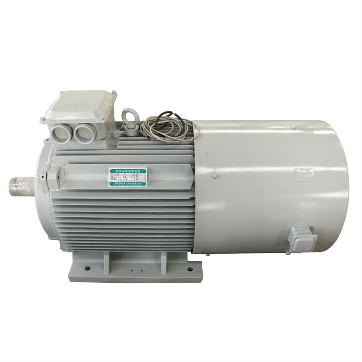
High shock resistance matters because a mining motor is exposed to the consequences of process instability, not just its normal operating point. A well-matched Mining Industrial Motor helps reduce the chance that a momentary impact becomes loosened hardware, bearing distress, insulation damage, or unplanned downtime. But the motor cannot solve a weak foundation, a misaligned coupling, or an uncontrolled jam by itself.
The strongest purchasing decision combines application data with an engineering review: define the transient events, check the complete load path, confirm the mounting and environmental conditions, and set practical acceptance criteria. For a Permanent Magnet Motor PMSM in mining service, that same discipline ensures that efficiency benefits are considered alongside mechanical resilience. Specify the duty first, then ask for shock-resistance capability to be assessed against that duty.